
I have some observations about ship building from using the Starbase Spaceship Creator (SSC) and watching others use it. Some of these issues might seem trivial or like bikeshedding (some are), but because deleting parts in the game or drastically changing their dimensions could break ships I thought it be would important to bring it up now. The following sections cover the changes I think would improve the experience.
Angled Beams
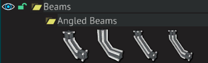
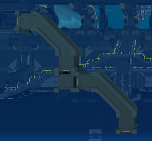
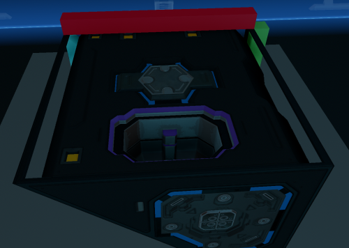
Angled beams don't allow builders to create continuous angled surfaces easily. The first thing designers start trying looks like this:
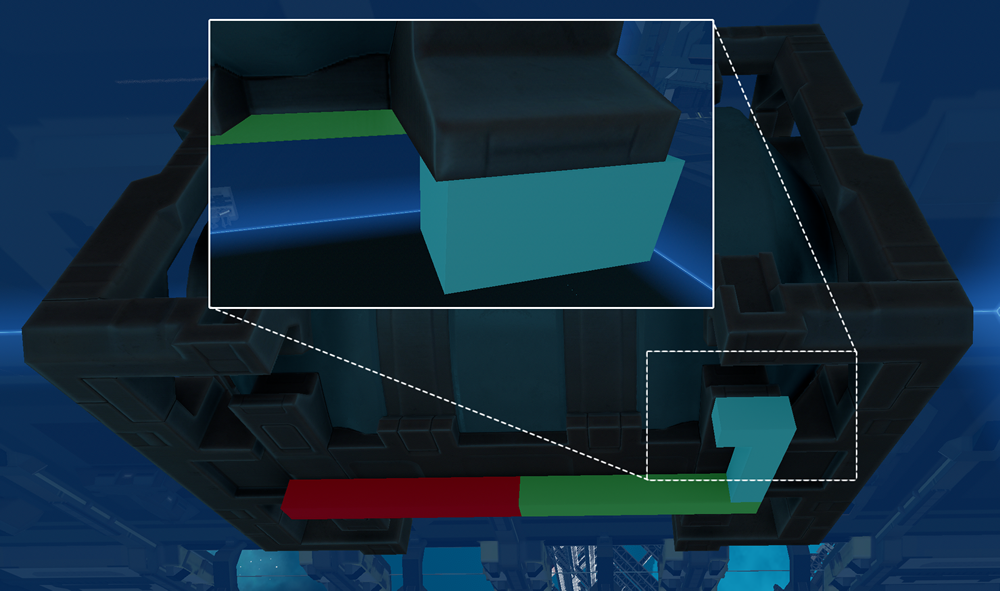
Designers then try using the 15, 30, and 45 degree special beams which are useful in a few cases, but have their own constraints and can introduce other problems. I've made different suggestions in the past about beams (that I now disagree with), but I think a more generic solution would be to add these 28 beams or a subset of them:

These replace those four angled beams currently available. This would offer designers a more flexible foundation even if specialized plating wasn't immediately supported. (That is they could build ships and then plate later).
Break apart fixed plate designs
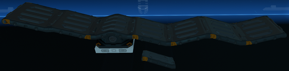
There's a lot of plate parts that are essentially plates that already exist combined with new unique plates. The plates I'm referring to are shown below.
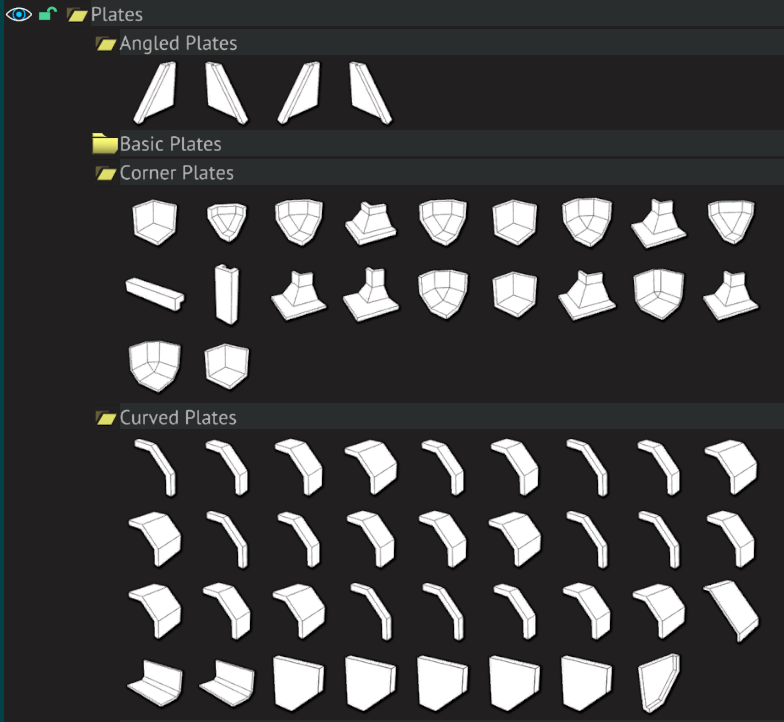
It's common for builders to construct a good beam structure that doesn't map to the fixed plating choices. Sometimes you want a curved plate, but without one or both of the basic plates on the ends. The corner plates are especially bad in this regard. They essentially overconstrain building such that you end up seeing similar designs on ships because it's the only configuration that works with the beams. In pretty much all cases the plates could be broken up into their smaller plates.
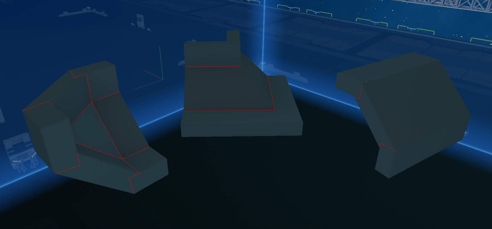
You'll notice in that image a lot of the cut pieces are just regular basic plates. By breaking them up it allows a lot more new configurations and uses. This is also more future-proof for later if different sloped beams are added.
Plate welding to simplify bolting
The idea of bolting seems practical and realistic, but in practice it's overly repetitive and doesn't feel meaningful. For reference, my simple ship is at 3,800 bolts and counting. Bolting differences are very minor which means auto-bolting everything is common. Because of plating size limitations, elegant bolting can be very hard without resorting to inside-out bolting - bolting from the beam to the plate. Small plates require a single bolt which need to align to a beam and can look random when you need multiple small plates to fill an area.
It's been brought up numerous times that plate welding - the ability to weld plates to each other and/or to beams - would make ship building faster without losing much. Beam welding already improved the process of building ships a lot and removed thousands of bolts. Plate welding would allow groups of plates to be connected seamlessly for building larger solid plates. Even if plates couldn't be welded to beams, this would save a lot of work on complex ships. This is also useful when building doors and movable plates which can have a lot of internal bolts holding them together. Right now, without the ability to temporarily hide plates, this is even weirder as you sometimes have to move plates to place bolts and the whole process is awkward.
It's also well known that plate welding would be amazing for windows. Right now they have seams, so using a bunch of small plates is not great visually as they have to be bolted somehow. Rather than a clean window one ends up seeing multiple individual panels and in some cases bolts and attachment plates which looks bad. (There's also glare issues).

There are a lot of fixed plate windows to get around this, but they're overly niche and probably shouldn't exist. If/when glass is a material later I think plate welding various window designs will be the only way to go for seamless windows.
I strongly think having plate welding would make ship building more approachable by allowing faster iteration by spending a lot less time bolting. I also think it's more future-proof if smaller plates are added like 12x12 triangle plates and some of the suggestions below which feature a lot of smaller plates. Plate welding also pairs well with decorative plates which often look terrible with visible bolts on them.
Non-clipping cables/pipes
People in the discord have talked about non-clipping cables for a while. New ship builders sometimes don't even know it's possible as the whole concept of running wires through a propellant tank, beams, batteries, generators, etc seems like a bug. Because of the lack of options, essentially every single ship uses clipping cables. This could be chalked up to alpha/Early Access, but it's not clear the developers are going to break everyone's ships when this is fixed.
I think there should be 3 types of cables and pipes. They'd all be 6x6 cm and wouldn't clip with any geometry in the game.
1. Cable/Pipes Embedded in Beams
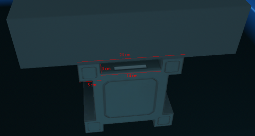
Before getting into the specific implementation suggestions for beams, I have one minor change. Right now beams are 24x24xN cm, yet they have 5x5 cm extrusions. (I'm referring to the 4 square features on the beams like in the image below). The game largely uses multiples of 12 cm so 6x6 cm would make more sense for the beam extrusions.
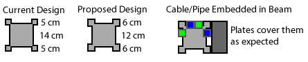
For cables the 6x6 cm would handle common situations like:
There would also need to be beam passthrough options to go from one side of a beam to the other.
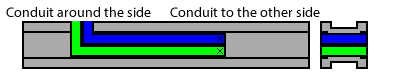
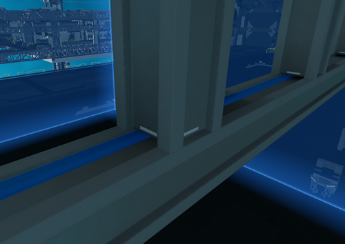
Ideally this would handle all the cases in ship where a person is running cables/pipes along beams. I'm imagining a system where users can click on snap points and drag in 6 cm increments to essentially paint the cable/pipe into the groove.
2. Cable/Pipes Embedded in Plates
Sometimes you want an aesthetic where pipes are running along the ceiling, floors, or the walls from buttons and such. This is basically my old cable/pipes in plates suggestion, but simplifying it to 12x6xN plates. This design requires a lot less new plates.

Builders could have the cable side facing inside the wall connecting to beam cables if they wanted. This allows cables/pipes embedded into plates to transfer across gaps or connect to a button that happens to be between two beams. (Or say running to lights in the ceiling).
3. Solid Conduits for Cable/Pipes
Solid cables and pipes would fill in the gaps between the above two systems allowing one to pipe in 3D space. The system would also support connecting beam and plate cables at various angles.
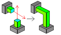
Builders would be able to click anywhere in a beam or plate at 6 cm increments and begin extruding conduit perpendicular from the surface and perpendicular from the edges of the conduit. Selecting two conduits would give the user the option to miter them which extends them until they connect. This handles cases where the conduits are built from surfaces with different angles.
(I haven't fully considered all the cases possibly so I might be missing edge cases).
Consistency between beams, plates, and devices.
The building system (plates, beams, etc) and the devices (generators, thrusters, machinery, etc) have two separate art directions.
The body of the thruster is 144x96 cm, but the nozzle is instead 142x96 leaving 1 cm gaps on two sides. On ships that attempt to plate around the nozzle this gap is visible. The sides of the box thruster also feature 12x12 cm bevels, but there's no 12x12 cm triangle plate to fill this. Ideally devices like thrusters should blend with the plating system in a more generic way so they can be incorporated into ship designs without appearing like monolithic separate features on the ship.
I haven't tried designing a ship with plasma thrusters, but when looking at designers that try it's less about a ship with plasma thrusters and more a ship around plasma thrusters. They take a lot of volume in a very specific place which imposes specific constraints. (Not to get off track, but I'd prefer more modules that can be placed around a ship's engines to support a thruster configuration rather than strict linear modules. Generators are a better direction even though they have strict adjacency rules).
The triangle thruster doesn't have gaps, but the corners have physical holes in them. There's a lot of detail that is more or less hidden on most ships.
My primary suggestion would be to use a 12 cm grid to design devices so everything aligns with plates. A 6 cm grid could be used for smaller features. I didn't measure the nozzle grates on the box thruster, but those would be a good example. Ideally they'd be 6 cm with 6 cm gaps. The diagonals grids on the triangle thruster would feature lines on a 6x6 cm grid.
Let's take a random device like a large hydrogen propellant tank. It's exactly 288 cm long (so a multiple of 12), and yet features of it aren't aligned to a 12 cm grid.
With this change of using a strict 12 cm grid would be the introduction of more snap points at 12 cm increments. This would make precision snapping faster for builders and more intuitive. Sometimes when moving plates around you expect certain snap points on devices that aren't there.
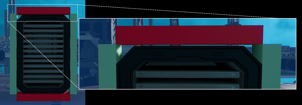
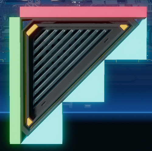
There are a few devices with very unique designs like the radiators.
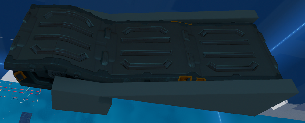
Their wavy design doesn't map well to triangle plates which makes them stand out. A lot designers found incorporating them into designs difficult, so they're kind of just placed haphazardly. I'm not completely against unique devices, but when builders look at a device they wonder about ways to make it aesthetically fit with a ship's theme, and radiators are definitely one of the bigger challenges. (It does fit well with some more organic designs).
Remove sockets
Many parts like lamps, hinges, slides, and larger devices that could be seamlessly embedded into walls often look out of place inside of ships as they feature strong bevels and visible sockets. Specifically on the battery and hinges this socket isn't aligned to the center which has visual asymmetry in designs.
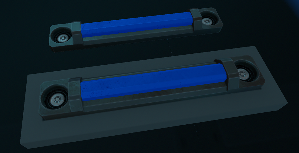
Lamps are I think the perfect example for why sockets aren't great. When you look at that image you'd think the socket should be on the back since the cables are ran in the walls, but they're designed with the thinking that ship builders are running wireless along the walls. This comes back to clipping as ship builders just click on the socket and run the cable behind. If clipping is removed you'd see cables on the ceiling from the sockets going into the wall anyway since that's how builders work. In any case the other issue is you still have two visible sockets so ship builders immediately look for ways to cover them which isn't ideal.
My suggestion would be to remove the sockets from all the devices and using the above embedded cable changes allow adjacent cables to connect automatically to devices. The sockets are generally in an arbitrary spot and devices can be rotated in a lot of ways making cabling to them without clipping not what the designer would want. In fact in a lot of ship designs the socket is flush next to a plate. (Allowing batteries and other devices to be flush with other surfaces is good, so forcing gaps just for cabling would be frustrating to work around). In the lamp example, removing the sockets would make it 48 cm more compact.
There are also a lot of cursed designs - using questionable connections with cables and progress bars - that would be a lot simpler by simply passing cables (and possibly pipes) through a device automatically. That is a beam/plate with embedded cables on one side of a hinge would automatically transfer through to a cable embedded on a beam/plate on the other side. (Slides on slides would just work by attaching them together). I digress, I have previous suggestions I'd make for slides/hinges here to make them more generic.
Positioning errors between parts
The building system has floating point precision issues when moving and snapping chains of objects. (This is really apparent when selecting and moving multiple objects). This leads to small gaps or overlapping between plates. Visually this results in lines on a ship's hull rather than appearing to be seamless.
In the SSC this can be mitigated by snapping parts off of one part in a long chain one part at a time, but it'll still happen using multiple long chains of parts that then connect back together at a shared part. This could be mitigated by assigning groups of parts to their own local 12 cm grid. Most ships are made up of just a few groups of parts which would mean a few independent 12 cm grids. (There are some very complicated ships that use a lot of 15 and 30 degree special beams where this would not help much at all with. I believe those builders have already accepted their fate, so it's not a huge issue for them).
There might be saner solutions for this that the developers could figure out. It's something that comes up quite a bit though. Even a button that automatically starts at one part and resnaps all the parts one at a time might be enough if it removes the errors.
Conclusion
The general part design is a really good start, but I'm slightly worried about locking into part choices that end up being fixed after alpha and overconstrain builders. My main worry is beginners will get frustrated they can't create what's in their head and give up. (I've seen this a number of times in livestreams where people undo a lot of work after beams or plates don't line up like they expect them to). The issues raised with the angled beams and curved plates for instance are pain points that nearly every beginner has run into. Removing those pain points and making part changes early before a lot of ships are broken is I think ideal.
Angled Beams
Angled beams don't allow builders to create continuous angled surfaces easily. The first thing designers start trying looks like this:
Designers then try using the 15, 30, and 45 degree special beams which are useful in a few cases, but have their own constraints and can introduce other problems. I've made different suggestions in the past about beams (that I now disagree with), but I think a more generic solution would be to add these 28 beams or a subset of them:
These replace those four angled beams currently available. This would offer designers a more flexible foundation even if specialized plating wasn't immediately supported. (That is they could build ships and then plate later).
Break apart fixed plate designs
There's a lot of plate parts that are essentially plates that already exist combined with new unique plates. The plates I'm referring to are shown below.
It's common for builders to construct a good beam structure that doesn't map to the fixed plating choices. Sometimes you want a curved plate, but without one or both of the basic plates on the ends. The corner plates are especially bad in this regard. They essentially overconstrain building such that you end up seeing similar designs on ships because it's the only configuration that works with the beams. In pretty much all cases the plates could be broken up into their smaller plates.
You'll notice in that image a lot of the cut pieces are just regular basic plates. By breaking them up it allows a lot more new configurations and uses. This is also more future-proof for later if different sloped beams are added.
Plate welding to simplify bolting
The idea of bolting seems practical and realistic, but in practice it's overly repetitive and doesn't feel meaningful. For reference, my simple ship is at 3,800 bolts and counting. Bolting differences are very minor which means auto-bolting everything is common. Because of plating size limitations, elegant bolting can be very hard without resorting to inside-out bolting - bolting from the beam to the plate. Small plates require a single bolt which need to align to a beam and can look random when you need multiple small plates to fill an area.
It's been brought up numerous times that plate welding - the ability to weld plates to each other and/or to beams - would make ship building faster without losing much. Beam welding already improved the process of building ships a lot and removed thousands of bolts. Plate welding would allow groups of plates to be connected seamlessly for building larger solid plates. Even if plates couldn't be welded to beams, this would save a lot of work on complex ships. This is also useful when building doors and movable plates which can have a lot of internal bolts holding them together. Right now, without the ability to temporarily hide plates, this is even weirder as you sometimes have to move plates to place bolts and the whole process is awkward.
It's also well known that plate welding would be amazing for windows. Right now they have seams, so using a bunch of small plates is not great visually as they have to be bolted somehow. Rather than a clean window one ends up seeing multiple individual panels and in some cases bolts and attachment plates which looks bad. (There's also glare issues).
There are a lot of fixed plate windows to get around this, but they're overly niche and probably shouldn't exist. If/when glass is a material later I think plate welding various window designs will be the only way to go for seamless windows.
I strongly think having plate welding would make ship building more approachable by allowing faster iteration by spending a lot less time bolting. I also think it's more future-proof if smaller plates are added like 12x12 triangle plates and some of the suggestions below which feature a lot of smaller plates. Plate welding also pairs well with decorative plates which often look terrible with visible bolts on them.
Non-clipping cables/pipes
People in the discord have talked about non-clipping cables for a while. New ship builders sometimes don't even know it's possible as the whole concept of running wires through a propellant tank, beams, batteries, generators, etc seems like a bug. Because of the lack of options, essentially every single ship uses clipping cables. This could be chalked up to alpha/Early Access, but it's not clear the developers are going to break everyone's ships when this is fixed.
I think there should be 3 types of cables and pipes. They'd all be 6x6 cm and wouldn't clip with any geometry in the game.
- Embedded into beams
- Embedded into plates
- Solid conduits for cable/pipes
1. Cable/Pipes Embedded in Beams
Before getting into the specific implementation suggestions for beams, I have one minor change. Right now beams are 24x24xN cm, yet they have 5x5 cm extrusions. (I'm referring to the 4 square features on the beams like in the image below). The game largely uses multiples of 12 cm so 6x6 cm would make more sense for the beam extrusions.
For cables the 6x6 cm would handle common situations like:
There would also need to be beam passthrough options to go from one side of a beam to the other.
Ideally this would handle all the cases in ship where a person is running cables/pipes along beams. I'm imagining a system where users can click on snap points and drag in 6 cm increments to essentially paint the cable/pipe into the groove.
2. Cable/Pipes Embedded in Plates
Sometimes you want an aesthetic where pipes are running along the ceiling, floors, or the walls from buttons and such. This is basically my old cable/pipes in plates suggestion, but simplifying it to 12x6xN plates. This design requires a lot less new plates.
Builders could have the cable side facing inside the wall connecting to beam cables if they wanted. This allows cables/pipes embedded into plates to transfer across gaps or connect to a button that happens to be between two beams. (Or say running to lights in the ceiling).
3. Solid Conduits for Cable/Pipes
Solid cables and pipes would fill in the gaps between the above two systems allowing one to pipe in 3D space. The system would also support connecting beam and plate cables at various angles.
Builders would be able to click anywhere in a beam or plate at 6 cm increments and begin extruding conduit perpendicular from the surface and perpendicular from the edges of the conduit. Selecting two conduits would give the user the option to miter them which extends them until they connect. This handles cases where the conduits are built from surfaces with different angles.
(I haven't fully considered all the cases possibly so I might be missing edge cases).
Consistency between beams, plates, and devices.
The building system (plates, beams, etc) and the devices (generators, thrusters, machinery, etc) have two separate art directions.
- Ship building plates have sharp polygon edges with angles in increments of 12 cm for the most part.
- Devices have beveled aesthetics and complexity. They have holes and various angle and curves. Some devices have lengths in increments of 12 cm, but there isn't a consistency everywhere.
The body of the thruster is 144x96 cm, but the nozzle is instead 142x96 leaving 1 cm gaps on two sides. On ships that attempt to plate around the nozzle this gap is visible. The sides of the box thruster also feature 12x12 cm bevels, but there's no 12x12 cm triangle plate to fill this. Ideally devices like thrusters should blend with the plating system in a more generic way so they can be incorporated into ship designs without appearing like monolithic separate features on the ship.
I haven't tried designing a ship with plasma thrusters, but when looking at designers that try it's less about a ship with plasma thrusters and more a ship around plasma thrusters. They take a lot of volume in a very specific place which imposes specific constraints. (Not to get off track, but I'd prefer more modules that can be placed around a ship's engines to support a thruster configuration rather than strict linear modules. Generators are a better direction even though they have strict adjacency rules).
The triangle thruster doesn't have gaps, but the corners have physical holes in them. There's a lot of detail that is more or less hidden on most ships.
My primary suggestion would be to use a 12 cm grid to design devices so everything aligns with plates. A 6 cm grid could be used for smaller features. I didn't measure the nozzle grates on the box thruster, but those would be a good example. Ideally they'd be 6 cm with 6 cm gaps. The diagonals grids on the triangle thruster would feature lines on a 6x6 cm grid.
Let's take a random device like a large hydrogen propellant tank. It's exactly 288 cm long (so a multiple of 12), and yet features of it aren't aligned to a 12 cm grid.
With this change of using a strict 12 cm grid would be the introduction of more snap points at 12 cm increments. This would make precision snapping faster for builders and more intuitive. Sometimes when moving plates around you expect certain snap points on devices that aren't there.
There are a few devices with very unique designs like the radiators.
Their wavy design doesn't map well to triangle plates which makes them stand out. A lot designers found incorporating them into designs difficult, so they're kind of just placed haphazardly. I'm not completely against unique devices, but when builders look at a device they wonder about ways to make it aesthetically fit with a ship's theme, and radiators are definitely one of the bigger challenges. (It does fit well with some more organic designs).
Remove sockets
Many parts like lamps, hinges, slides, and larger devices that could be seamlessly embedded into walls often look out of place inside of ships as they feature strong bevels and visible sockets. Specifically on the battery and hinges this socket isn't aligned to the center which has visual asymmetry in designs.
Lamps are I think the perfect example for why sockets aren't great. When you look at that image you'd think the socket should be on the back since the cables are ran in the walls, but they're designed with the thinking that ship builders are running wireless along the walls. This comes back to clipping as ship builders just click on the socket and run the cable behind. If clipping is removed you'd see cables on the ceiling from the sockets going into the wall anyway since that's how builders work. In any case the other issue is you still have two visible sockets so ship builders immediately look for ways to cover them which isn't ideal.
My suggestion would be to remove the sockets from all the devices and using the above embedded cable changes allow adjacent cables to connect automatically to devices. The sockets are generally in an arbitrary spot and devices can be rotated in a lot of ways making cabling to them without clipping not what the designer would want. In fact in a lot of ship designs the socket is flush next to a plate. (Allowing batteries and other devices to be flush with other surfaces is good, so forcing gaps just for cabling would be frustrating to work around). In the lamp example, removing the sockets would make it 48 cm more compact.
There are also a lot of cursed designs - using questionable connections with cables and progress bars - that would be a lot simpler by simply passing cables (and possibly pipes) through a device automatically. That is a beam/plate with embedded cables on one side of a hinge would automatically transfer through to a cable embedded on a beam/plate on the other side. (Slides on slides would just work by attaching them together). I digress, I have previous suggestions I'd make for slides/hinges here to make them more generic.
Positioning errors between parts
The building system has floating point precision issues when moving and snapping chains of objects. (This is really apparent when selecting and moving multiple objects). This leads to small gaps or overlapping between plates. Visually this results in lines on a ship's hull rather than appearing to be seamless.
In the SSC this can be mitigated by snapping parts off of one part in a long chain one part at a time, but it'll still happen using multiple long chains of parts that then connect back together at a shared part. This could be mitigated by assigning groups of parts to their own local 12 cm grid. Most ships are made up of just a few groups of parts which would mean a few independent 12 cm grids. (There are some very complicated ships that use a lot of 15 and 30 degree special beams where this would not help much at all with. I believe those builders have already accepted their fate, so it's not a huge issue for them).
There might be saner solutions for this that the developers could figure out. It's something that comes up quite a bit though. Even a button that automatically starts at one part and resnaps all the parts one at a time might be enough if it removes the errors.
Conclusion
The general part design is a really good start, but I'm slightly worried about locking into part choices that end up being fixed after alpha and overconstrain builders. My main worry is beginners will get frustrated they can't create what's in their head and give up. (I've seen this a number of times in livestreams where people undo a lot of work after beams or plates don't line up like they expect them to). The issues raised with the angled beams and curved plates for instance are pain points that nearly every beginner has run into. Removing those pain points and making part changes early before a lot of ships are broken is I think ideal.
Last edited: